 In developing the products we seek to understand all aspects of the product use from specification, delivery, installation, use and ongoing maintenance. We look at flexibility, ease of use, cost and robustness along each step from product specification to use. For our first control head we got input from the faculty and students of KPU for the look and feel of the product. We look forward to working with them in the future as we extend our product line.
The general architecture uses a number of micro processors to reflect the structure of the vessel. Rather than one massive CPU to control all functions each device CPU communicates and co-ordinates functions along the dedicated CAN-BUS. The system is designed to failover. If the primary CPU loses its power then a second CPU takes over as the primary system on the CAN BUS.
The simplicity in design is reflected in reducing the number of mechanical parts that break down. It also means that we chose to use a hard wired USB (Laptop/Smartphone) interface. The interface uses a simple graphical menu system for you to review and configure the system. We choose the USB as it is more secure and simpler than a keypad or a Bluetooth or other open interface.
Preliminary product testing is being done to marine standards EN 60945. A control head or a CPU does not make a system! Based on your requirements the components will be assembled and configured to match the functions of your vessel. In addition to individual product testing, system drawings and configuration are specified and then the system goes through a final system test before shipping.
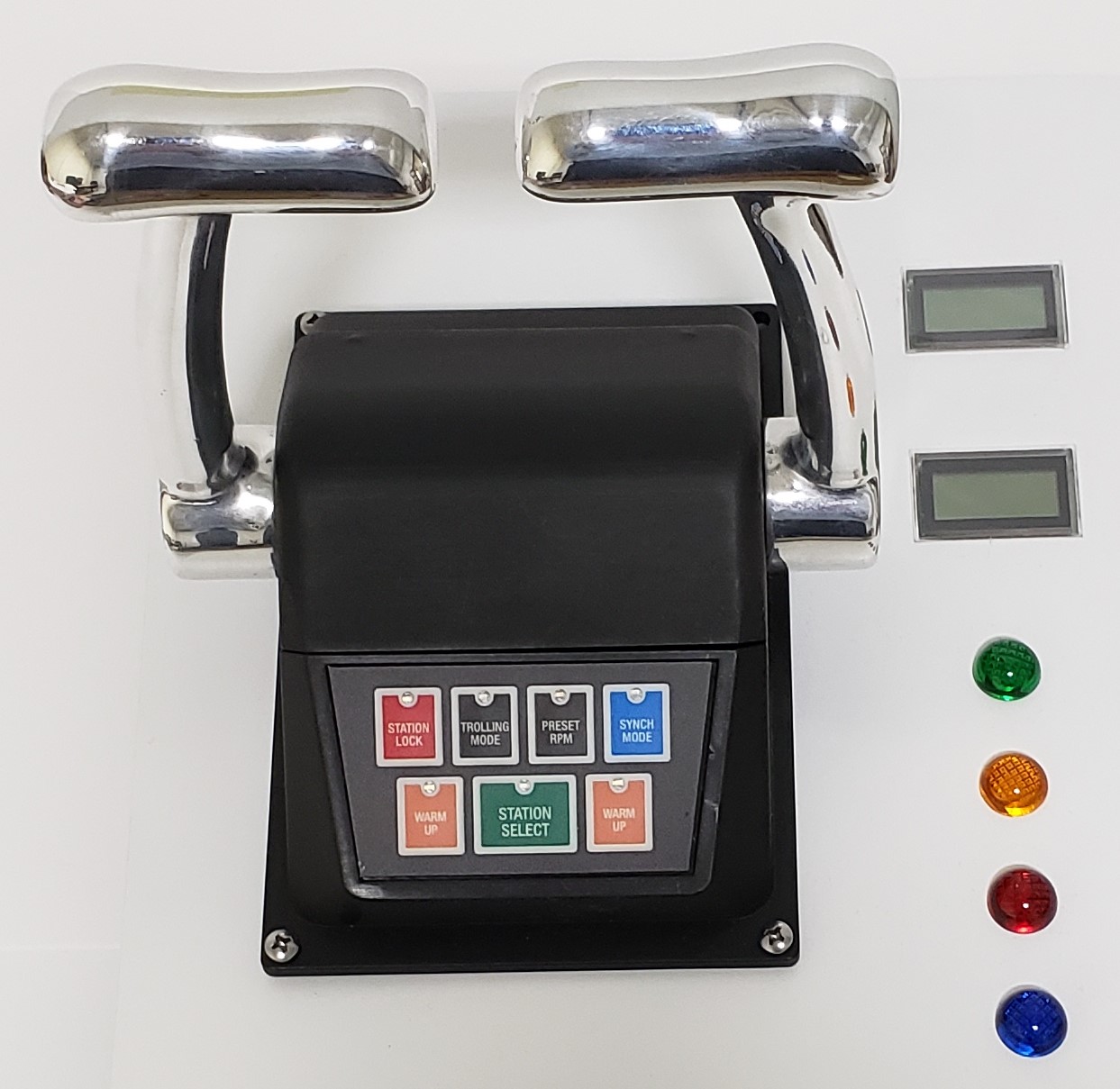
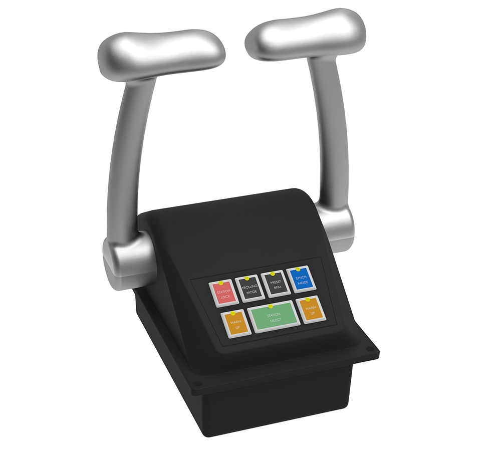
1010 - Twin Engine Control Head
The twin Engine control head has two handles for twin engines and an optional third input for a third engine, steering, or a bow / stern thruster. The control head reports the requested command via the CAN BUS to the Device Controls and reads back the station in command and current state of the system.


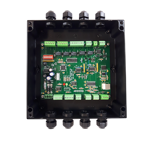
1020 - Device Control
– Each device control in the system can be set to one of four modes:
– Slave mode – where it gets commands and reports back from a master CPU this would be used for more complex systems.
– Fixed Propeller Mode – where the outputs are for an Engine (4-20ma or PWM); Trolling Gear, a reverse reduction gear as well as an optional on/off relay for a shaft brake, PTO or to signify trolling mode. The system will report back engine RPM.
– Controllable Pitch Propeller Mode – the outputs is used for one Engine (4-20ma or PWM); pitch control (4-20ma) and an ON-OFF gear as well as an optional relay for PTO. The system will report back engine RPM and engine load.
– Steering Mode – the outputs can be used to control steering via ON/OFF relays as well as 4-20 for proportional control. The system will report back the rudder angle.


